
Duct By Cloud
This is a post about the new tool DuctByCloud included in the new release 1.22 of cloud2model. This new tool is very similar to PipeByCloud, except for the dual functionality for both rectangular and circular sections.
DuctByCloud is a smart tool for fast creation of rectangular and circular ducts with just two clicks on the apparent visible side of the duct in the point cloud. It has near instantaneous detection of the section dimensions, feedback about the level of confidence of the automatic detection and several options for further geometrical regularization.
In combination with PipeByCloud, this new tool enhances greatly the functionality of cloud2model in MEP Scan2BIM workflows.
Before using the tool.
We will prepare in advance a 3D view with a section box of the area containing the visible pipes in the point cloud.
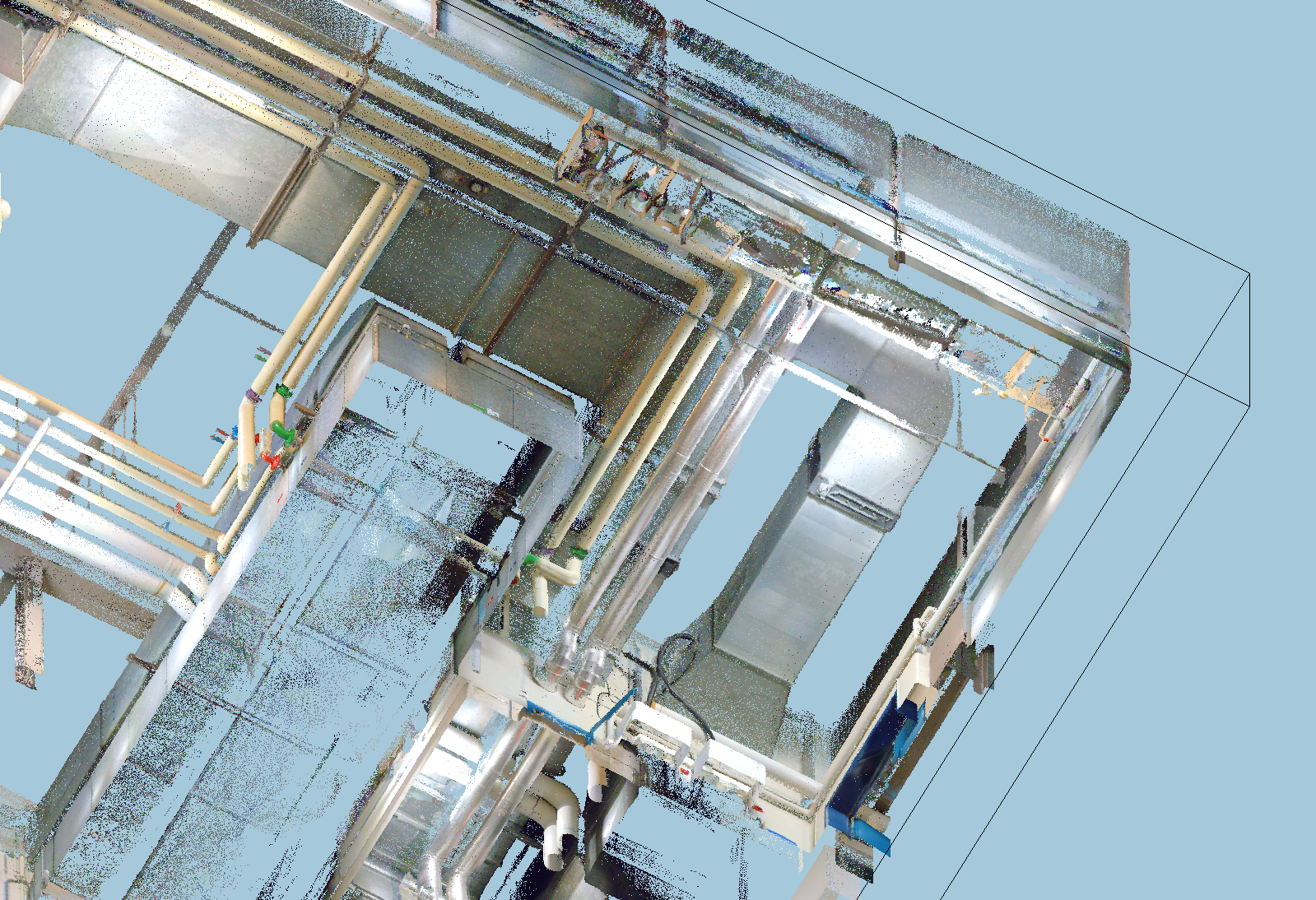
The minimum view extension the better. If we have several rooms of delimited areas with ducts, it is better to work individually with each area or room.
When pointing in the screen to the apparent visible side of the duct in the point cloud, it would help if we don’t have other visible objects visible on front of the ducts. These objects can block the actual visibility of the side of the duct recorded in the point cloud. For this reason it is recommended to limit the depth of the 3D view to the minimum needed.
DuctByCloud can only be used with 3D views with section box. If you have already a cropped 2D view floor plan/RCP/section with the area to study, you can use the cloud2model tool 3D<>2D to automatically get a 3D view with the a section box matching the 2D view (or the other way around). Additionally, the tool DynamicView can help greatly to adjust the 3D view section box.
Options.
The new tool will open a separate window with all the available settings.
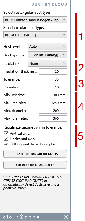
1 Main options for the new ducts created.
Rectangular duct type to use from the types available of the current project.
Circular duct type to use from the types available of the current project.
Host level. We have three auto options or we can directly select any current floor level. The auto options are:
“Auto”, closes level to the axis middle point.
“Auto lower”, closest lower level to the axis middle point.
“Auto upper”, closest upper level to the axis middle point.
Duct system to assign for the new created ducts.
2 Insulation options.
We can set if we want to consider insulation. In this case, the detected dimensions will be assumed as the outer global dimensions of the duct+ insulation. We can select from the types of insulations defined in the project.
The insulation thickness to use if we have set any kind of insulation.
3 Geometrical tolerance and rounding.
Tolerance to consider for the geometrical regularization (see bellow)
Rounding of the exact diameter detected.
4 Dimensions range for automatic detection
Minimum rectangular size to be detected.
Maximum rectangular size to be detected.
Minimum diameter to be detected.
Maximum diameter to be detected.
5 Geometrical regularization
If the axis is near vertical, force to be perfectly vertical if in tolerance.
If the axis is near contained in a horizontal plane, force to be perfectly horizonal if in tolerance.
If the axis is close to follow in floor plan the main orthogonal directions of the project, force perfectly orthogonal directions in floor plan.
Creating new ducts.
We can start to automatically detect ducts with “CREATE RECTANGULAR DUCTS” and “CREATE CIRCULAR DUCTS”.
We will click two points in the apparent visible surface of the duct and a new duct will be automatically created, with automatic detection of the section dimensions and axis.
We can continue clicking two points and creating new ducts until pressing the Esc. key at any moment to stop the command.
Each new duct created with appear as a separate command in the undo command list. We can undo the last(s) duct(s) created without cancelling all the pipes created in the command.
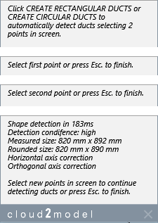
The feedback area of the tool window gives information about the current step in the process and about the created duct:
Level of confidence of the automatic detection (high, medium, low).
Exact dimensions detected.
Actual rounded dimensions of the new duct.
Any geometrical regularization.
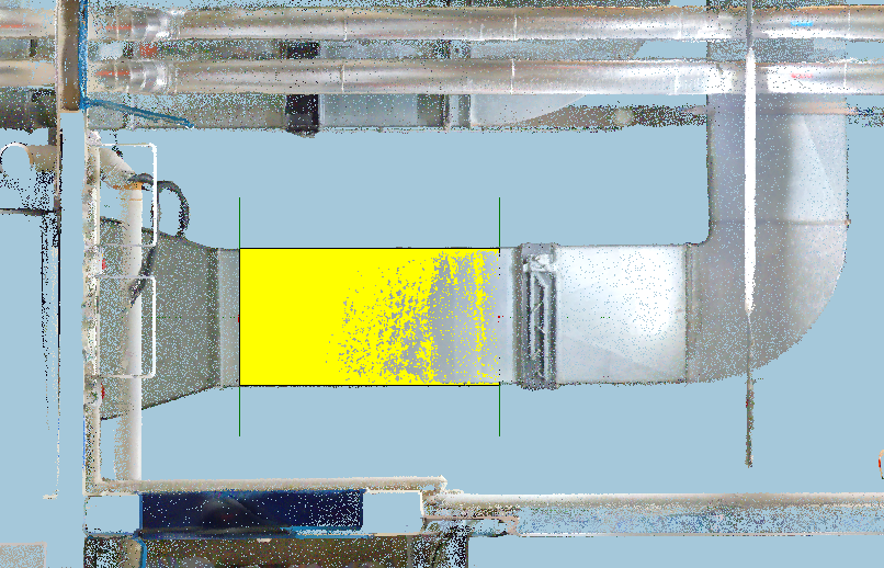
Additionally, we have some visual feedback in the 3D view.
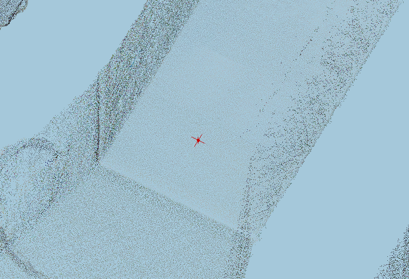
A small red cross in each of the two point clicked in the screen. This allows visual feedback about the actual point recognised in the apparent visible surface of the pipe in the point cloud.
After the new pipe is created, a big cross in the duct ends with a different color depending of the level of confidence: green for high, orange for medium and red for low. This complements the text info in the feedback area of the tool window.
The visual feedback in the 3D view is temporal and it will disappear when we stop the command pressing escape.
If after selecting the 2 points, no duct is automatically detected, we will get a notification error in the feedback area.
.
Best workflows in using the tool.
When clicking the 2 points in screen please follow the next guidelines.

Tipically the ducts will be close to a surface (wall or ceiling). For rectangular ducts, only three sides will be recorded by the point cloud.
We will use a view with the duct surfaces being visible from outside. Ideally the view orientation will be parallel to the normal direction of the main or central surface of the duct (first from the left).
The view can be a bit tilted from the ideal orientation (second from the left).
It is important to avoid that the view orientation is too tilted, or close to be perpendicular from the ideal orientation (second from the right).
Never use a point of view that the duct surfaces are visible from inside (first from the right).
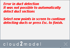
For circular ducts the surface recorded in the point cloud will be 180° or less.
The duct surface must be visible from the exterior or convex side. Ideally the view orientation will be parallel to the normal direction in the middle part of the surface (first from the left).
The view can be a bit tilted from the ideal orientation (second from the left).
It is important to avoid that the view orientation is too tilted, or close to be perpendicular from the ideal orientation (second from the right).
Never use a point of view that the duct surface is visible from inside or concave side (first from the right).
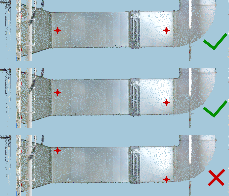
In rectangular ducts, we will click the points in the central part of the exposed side.
It is better to avoid to select the points close the the lateral side.
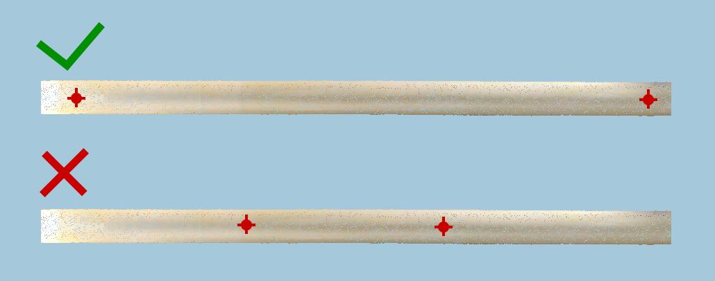
With circular ducts, we will click the points close to the imaginary center line of the visible surface.
It is no needed that the two points are perfectly in the center, but it is is better to avoid points too close to the sides of the visible surface.

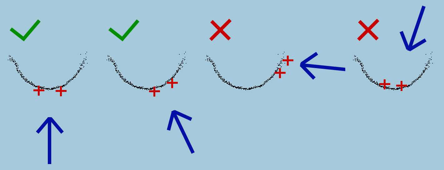
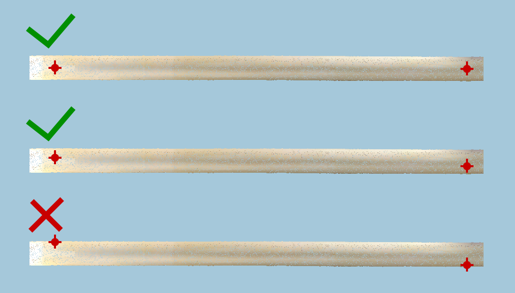
In order to easily click the points in the central part of the visible surface, it would be helpful if we orientate the 3d view in a way that the visible surface of the pipe is more or less frontal to the direction of the view.
Ideally, the direction of the point of view will be parallel to the normal direction of central part of the visible surface of the pipe, like in the upper image.
If the view is a bit tilted (middle image), it will be ok. But we must avoid point of view orientations like in the lower image.
When a new duct is created, its extension will follow the original two points clicked. Although is very easy in Revit to extend the duct afterwards, we must always remember that the geometry regularization check the actual duct length related to the original 2 points. This means, that maybe it can be regularised being in tolerance with the length by the original 2 points, but after it is extended it could be not in tolerance anymore.
If we have the regularization settings on, it is convenient to click the points covering most of the actual length of the pipe.
In general the most problematic point clouds artifacts in ducts are reflections. If in the visible duct surface we see big differences in the apparent brightness, it is recommended to avoid to click points in the most bright (near white) areas.
It is very convenient to set the dimensions range (min. and max.) as limited as possible. We must avoid minimum sizes too small or a lot smaller than the ducts to detect. And the same way, we must prevent maximum sizes too big or a lot bigger than the ducts to detect. If the possible dimensions range does not much the actual ducts sizes to detect, we can have issued of detection accuracy or wrongs detections.
The level of confidence feedback is set depending on:
Similarity of the diameter detected for both points.
Internal consistency in the automatic detection for each point.
If the level of confidence is other than high, it is mostly because too much difference in the diameter measured in each point. A detection with medium level will probably be ok, but with low level it is recommended to check the result.
Current limitations or known issues.
The duct with oval sections are not supported.
The ducts with cross section rotation are no supported.
It can happen that the lateral sides of a rectangular duct are only partially recorded in the point cloud because other elements (another ducts or pipes) block the view from the scanning device.
In order to automatically detect the lateral size dimension it is needed that at least one full lateral side is recorded in the point cloud. If both are only partially visible, the lateral size dimensions detected will be of the visible part. If it is smaller than the minimum rec. size, the minimum will be used.

Some big ducts have their exposed side formed with a combination of triangular faces (left), instead of a continues planar face (right). The different normal orientation of each triangular face can produce some issues in the automatic detection. The recommended workflow in this case is to try to click in different parts until reaching a correct detection.
Checking the result.
The coud2models tools CrossSection and LongSection have been updated in order that they can be used with ducts.

With CrossSection we will click a duct, with automatic creation of the cross section in the point clicked.
With LongSection we will click a duct, with automatic creation of a longitudinal section of the whole extension of the duct clicked.
Please take into account the rounding dimensions and the geometry regularization can result in some deviation between the precise axis and dimensions detected and the actual duct created.