
Smart Equipment

This is a post about the new tool SmartEquipment included in the new release 1.22 of cloud2model.
SmartEquipment is the second tool of cloud2model related to transform in-place Revit families to conventional external families. Instead of a general tool like In-PlaceToExternal, it is thought for the specific case scenario of MEP equipment to be connected with several pipes and/or ducts. The tool automatically creates any needed MEP connector in the new external family. And additionally, it automatically connects the MEP elements with the inserted instance of the new family.
The tool supports singular connection scenarios, like for example if the axis of the pipe or duct segment is no perpendicular to the face they connect to. Or if the duct cross rectangular section is rotated or tilted. And it allows, if needed, to manually refine the solid geometry related to the connectors
The options for setting the coordinate system reference and hosting of the new family has been simplified in comparation with In-PlaceToExternal, for a faster and simpler workflow for this specific case scenario.
Before using the tool.
The current active view will be a 3D view that allows to easily select both the in-place family and the pipe/ducts to connect. It is recommended:
Minimum view extension and number of elements visible in screen.
Only the actual pipes and ducts segments that connect are visible. This can be very helpful if we have complex routing with many pipes/ducts segments and accessories. If we leave everything visible, maybe we will select by error some pipes/ducts segments that are not the ones to connect.
Some transparency to easily check the position/orientation of the Coordinate System Reference (CSR). We can use, for example, cloud2model Trans.1 or Trans.2 in the visibility tool group.
The geometry of the family in place that represent MEP equipment must be finished of at least of anything related to the faces that the pipes/duct are going to connect. Note: it is no needed to create in advance any kind of geometry element for the connectors, everything will be automatically done by the tool.
The axis of the pipes/duct segments to connect must be in the correct position.
Basic workflow.
The new tool will open a separate window with all the needed commands and settings involved in the process. The workflow steps are similar to In-PlaceToExternal, but with simplifications related to the Coordinate System Reference (CSR) and the hosting options. And there are some additional settings related to the geometry of the connectors.

1 Preliminary steps before creating the external family.
Set path of the family template to use.
Set path to save the new external family.
Select in-place family with automatic insertion of the CSR
Select pipes and ducts to connect
Please notice that these steps are enumerated in the feedback area, with “Pending” or “Ok”.
2 Create the external family with the needed connectors.
After all the preliminary steps are done, we can create the external family. Before clicking the button we can check the settings for the offset of the connectors geometry in relation to the face that will contain them.
3 Insert the new external family and connect with the selected pipes/ducts.
After the new family is created with can finish with automatic insert of an instance exactly in the same position as the in-place family and automatic MEP connection with the selected pipes/ducts.
File paths.
In the same way as In-PlaceToExternal, we will use “SELECT FAMILY TEMPLATE”” for browsing in a select file dialog the family template to use. And “SAVE NEW FAMILY TO” to set where to save the new family in a conventional save file dialog. Alternatively, we can directly write (or copy and paste) the paths in the text fields.
The last paths used will be remembered when using the tool more than one time in the same Revit session. There is no need to browse and select the same family template each time.
The tool is thought for creating families with conventional geometrical reference. It is assumed that the family template to use will be generic model, mechanical equipment or speciality equipment. The simplest workflow is to select generic model and later change the category of the family if needed.
Automatic insert of the CSR.
One of the main differences with In-PlaceToExternal, is that the managing of the Coordinates System Reference or CSR is greatly simplified. When selecting the in-place family, the CSR will be automatically inserted. The X and Y position will be of the volumetric center of the in-place family, with the Z position of its lower limit. The orientation of the axis will be like the general directions of the project.
In most of the cases there will be no need to adjust the automatic position and axis orientation of the CSR. But we can always manually move or rotate the CSR if we prefer another point for the local origin of the family, or that its local X and Y axis are not aligned with the general directions of the project. As explained above, some transparency in the view will greatly help to manually edit the position and orientation of the CSR.
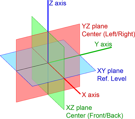
In the same way as In-PlaceToExternal the Coordinates System Reference or CSR define the local origin and the orientation of the base level plane and the two center planes. The CSR is an adaptive component of one placement point with explicit visual feedback of all the axis and planes involved.
We use the conventional RGB colors for the axis and planes (same color as the perpendicular axis):
X red axis
Y green axis.
Z blue axis.
XY (Ref. Level) blue plane.
XZ (Front/Back) green plane.
YZ (Left/Right) red plane.
Selecting the pipes and ducts.
When selecting the MEP elements to connect, we can select objects of category Pipe or Duct with rectangular or circular section. When we finish the selection, the tool will check if the selected elements can be connected:
The element axis is a straight line.
The element axis intersects the in-place family. Or if we extend one of the axis ends, it is possible to find a geometrical intersection.
The element axis is not totally inside the in-place family. It can be an overlap but part of the axis must be outside.

If there are selected elements that do not match the above conditions, we will get a warning dialog and the related objects will be highlighted in the screen.

If at least one element match the conditions, we will get Ok feedback, with a confirmation of the number of pipes/ducts found.
Please notice that the command “SELECT PIPES AND DUCTS” will be inactive until the in-place family is selected. Because of the check of the possible intersection, It is needed to select first the in-place family and later the pipes and ducts.
Creating the new family with the connectors.
After all the preliminary steps are done, the command “CREATE FAMILY WITH CONNECTORS” will create the external family with the the geometry of the in-place family and any needed connector.
For each selected pipe/duct, it will be created an additional solid object which outer face will host the MEP connector:
For pipes, it will be a cylindrical extrusion, with a diameter of the outer dimensions of the pipe. The pipe MEP connector will have the diameter dimension of the pipe.
For ducts of rectangular shape, it will be a rectangular extrusion with the width and height dimensions of the duct. The local X and Y directions of the extrusion sketch will match the actual directions of the duct section, for perfect alignment in the case that the duct cross section is rotated or tilted in relation with the main directions of the project. The duct MEP connector will have the width and height dimensions of the duct.
For ducts of circular shape, it will be a cylindrical extrusion, with the same diameter as the duct. The duct MEP connector will have the same diameter.

With the two offset settings, outer offset (OutOff) and inner offset (InnOff), we can control if the auxiliar connector solid will stick out of the equipment, or if it will remain perfectly flat. In this last case, the connector solid will overlap the solid of the equipment. In order to have clean solid geometry the equipment solid will be cut or subtracted of the volume of the connector solid.
We can differentiate 3 possible scenarios:

1 Planar face and perpendicular axis.
This is the more common case.
InnOff > 0 and OutOff = 0. Flat connector. In this case we have solid overlap and the equipment solid will be cut or substrated.
InnOff = 0 and OutOff > 0. Sticking out connector. There is no solid overlap.
InnOff > 0 and OutOff > 0. Sticking out connector with solid overlap. To have solid overlap if the solid connector will stick out seems unnecessary. But these settings can be very convenient if not all the connections must be equally flat or sticking out. After the external family is automatically created, we can manually edit it, changing the aux. connector solids to be flat when needed.

2 Planar face and no perpendicular axis.
This is singular case. The aux. connector solid will always stick out of the equipment face and the InnOff setting will be ignored.
OutOff = 0. Minimum length for clean geometry depending of the angle between the face and the axis.
OutOff > 0. Additional length beyond the minimum.

3 No planar face.
This is another singular case, like for example a convex cylindrical surface. Tipically we will have both OutOff > 0 and InnOff > 0. Sometimes it can be difficult to know in advance what is the convenient InnOff value. But we can always easily modify the aux solids after the family is created.
Important to renember:
Both OutOff and InnOff can not be = 0 at the same time.
Both OutOff and InnOff must be positive.
If we edit manually the aux solids afterwards, we can graphically stretch the grip of the face that contains the connector or change numerically the extrusion values, that can be more convenient for changing several aux solids at the same time. In this last case take into account that “Extrusion End” will be InnOff and “Extrusion Start” will be OutOff but negative.
Finally, as in In-PlaceToExternal, we have the option of directly opening the new family in the family editor after the family has been created.
Insert and connect.
Like in In-PlaceToExternal, the last step of the process is to replace the original in-place family with an instance of the new created family exactly in the same position and orientation. This is done automatically with the command “INSERT AND CONNECT”, that will make too the actual MEP connections between the selected pipes/ducts and the related MEP connectors.
The hosting options has been simplified compared with In-PlaceToExternal. The new instance will be always hosted in the closest floor level to the lower limit of the equipment solid geometry. But we maintain the same additional settings, that tipically we will leave always with the default values:
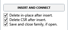
To delete the original in-place family.
To delete the adaptive component that represent the CSR used.
If the new family is open in the family editor, to save it and close it.
When connecting the pipes/ducts with the related connectors defined in the family, one of the ends of the pipe/duct segment will remain linked to the connector point. This means that if we edit the aux. connector solids (as explained above) after the family is inserted and all the elements connected, the length of the pipes /ducts will automatically adjust when reloading the family in the project.